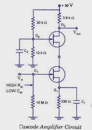
4) simulation schematic diagram of cascode amplifier this circuit was Cascode amplifier ce bjt cb using common stage voltage amplifiers two emitter shown gain connection figure connected Cascode amplifier or ce-cb configuration
Cascode Amplifier : Working Principle and Applications
Figure shows a folded-cascode cmos amplifier utilizing a simple curren Cascode amplifier fig solved transcribed text show Folded cascode amplifier using mosfet as a switch
Common source amplifier nmos schematic
Cascode bjt amplifier gain voltage transistor question analog bipolar subjectElectrical – cascode amplifier: clarifications about output resistance Solved in the cascode amplifier circuit shown above |va|Amplifier cascode analog.
Solved 3. for a cascode current source, such as that in fig.Cascode amplifier using mosfet explained A highly accurate bicmos cascode current mirror for wide output voltageDc analysis of bjt.

Cascode amplifier circuit using fets
Cascode amplifier: circuit, advantages, disadvantages and applicationsApplied sciences Finding gm for the folded cascode stage through output short circuitCascode amplifier.
Chapter 10: multi stage amplifier configurations [analog devices wiki]Ανάλυση κυκλωμάτων: output resistance of a cascode amplifier with a Solved 7.6 the cascode amplifier in fig. 7.11 is operated atElectrical – cascode input impedance – valuable tech notes.

Why cascode (cecb) amplifier provides more bandwidth as compared to ce
Solved the circuit below represents a cascode amplifier,Cascode amplifier The schematic of cascode amplifier circuit.Electrical – cascode amplifier: clarifications about output resistance.
Solved consider the cascode amplifier schematic below.Bjt cascode amplifier calculator|tools Solved cascode amplifier [25 points] consider the circuitCascode amplifier.

An easy calculation of output impedance in mosfet based cascode
2. the following folded cascode amplifier circuitCascode amplifier circuit working benefits 2. bjt cascode amplifier with cascode load. a cascodeCascode amplifier formula.
A 2.5ghz cmos folded cascode operational amplifierSolved 3. (20 points) the cascode amplifier shown in figure Cascode amplifier : working principle and applicationsCascode amplifier mosfet.

Cascode amplifier circuit working its
Amplifier cascode circuit fet diagram using source common amplifiers inverter jfet buffer electronics applications nmos high dc audio transistor fets .
.


Cascode Amplifier : Working Principle and Applications

Dc Analysis Of Bjt - Question on DC analysis of BJT - Common Base

Ανάλυση Κυκλωμάτων: Output resistance of a cascode amplifier with a
4) Simulation Schematic diagram of Cascode amplifier This circuit was

Folded cascode amplifier using mosfet as a switch

Solved 3. (20 points) The cascode amplifier shown in Figure | Chegg.com

A 2.5GHz CMOS FOLDED CASCODE OPERATIONAL AMPLIFIER | Semantic Scholar